Background
S/V Dancy just underwent a repower and fuel tank replacement in 2008. The entire engine room and equipment space were reconfigured. All plumbing, electrical, steering, fuel handling, etc. were renewed along with the new engine, transmission, flexible coupling, shaft, dripless log, and cutlesses. While the engine was out the port fuel tank was replaced with a new 65 gallon aluminum tank. The starboard vertical tank was replaced with a 100+ gallon horizontal tank.
Originally when purchased (10/2007) the boat had 110 volt refrigeration powered through the inverter when off of shore power. This setup worked very well but was a horrendous amp consumer, so that system was replaced with a custom air & water cooled 12 volt unit and that made Dancy a 12 Volt boat. The only AC power needed was for the water heater and the 110 volt outlets. Both of these items can be powered through the Trace 2500 watt inverter.
After finishing the repower and taking a short trip out to Catalina, while sitting at anchor and running the main engine to charge the batteries, it occurred to me that this was a ridiculous waste of money we had just spent on this brand new engine. So while solar panels are planned and alternative energy sources will be pursued, we needed a way to charge the batteries without running the main. I looked at the Fischer Panda (Too finicky and expensive), the AquaMarine Unit (nice but expensive) and a couple of others. After looking at these units I figured it wouldn't be that difficult to build one myself. So that's how this project began.
Sourcing the Parts
The first thing to do was to source the parts. The engine for this was going to be a Kubota EA330. It is a single cylinder 7 hp liquid cooled diesel engine. It turns out that purchasing one of these can be a challenge due to Kubota's distributor and dealer agreements. I finally had to order one from the local distributor in Phoenix. I ended up with the EA330 APU engine. This engine is a base engine meant to be sold as an OEM unit to be built into an APU mainly for the trucking industry.
As such it had no exhaust, air cleaner, fuel tank, PTO stub shaft or any other external accessories. Most of this is ok because I was going to marinize it anyway. The engine came with an air cooled radiator that had to be replaced with a marine heat exchanger. There are two sources for this and only one was willing to sell me the parts. Next Generation was willing to sell me any parts I wanted without asking if I had one of their units or not. Next Generation builds a 3.5 KW AC Marine genset based upon this engine, so after reviewing their manual and parts list, I had found a source for a lot of the items that would be very difficult to build or source.
From Kubota I bought:
The EA330, separate PTO Stub Shaft and a service manual.
From Next Generation I bought:
Bronze Heat Exchanger, SS exhaust can with water injection, throttle solenoid and linkage, electric fuel pump, raw water pump and drive gears, original Kubota start shaft and internal start gear (drives the water pump and shaft has been discontinued on the new engines), oil pressure switch, H20 temperature switch, misc. hoses, mounting base for solenoid & fuel pump, water pump belt & belt guard.
Other suppliers:
From Grainger's I bought the motor sheaves. From Zena Mobile Welders I bought a 150 amp 12 volt welding generator (basically an alternator with large diodes, bearings). From Dultmeier Sales I bought a bronze head high pressure pump with a 12 volt clutch pulley. From Front Panel Express I ordered a control panel (designed on their free design software, a great source for all kinds of panels.). From Del City I purchased the Control panel switches LEDs, and misc. electrical parts. A magnetic tachometer and pickup with an hour meter plus a temperature gauge and sender plus a Blue Seas Digital Multimeter came from Port Supply.
Assembly Process
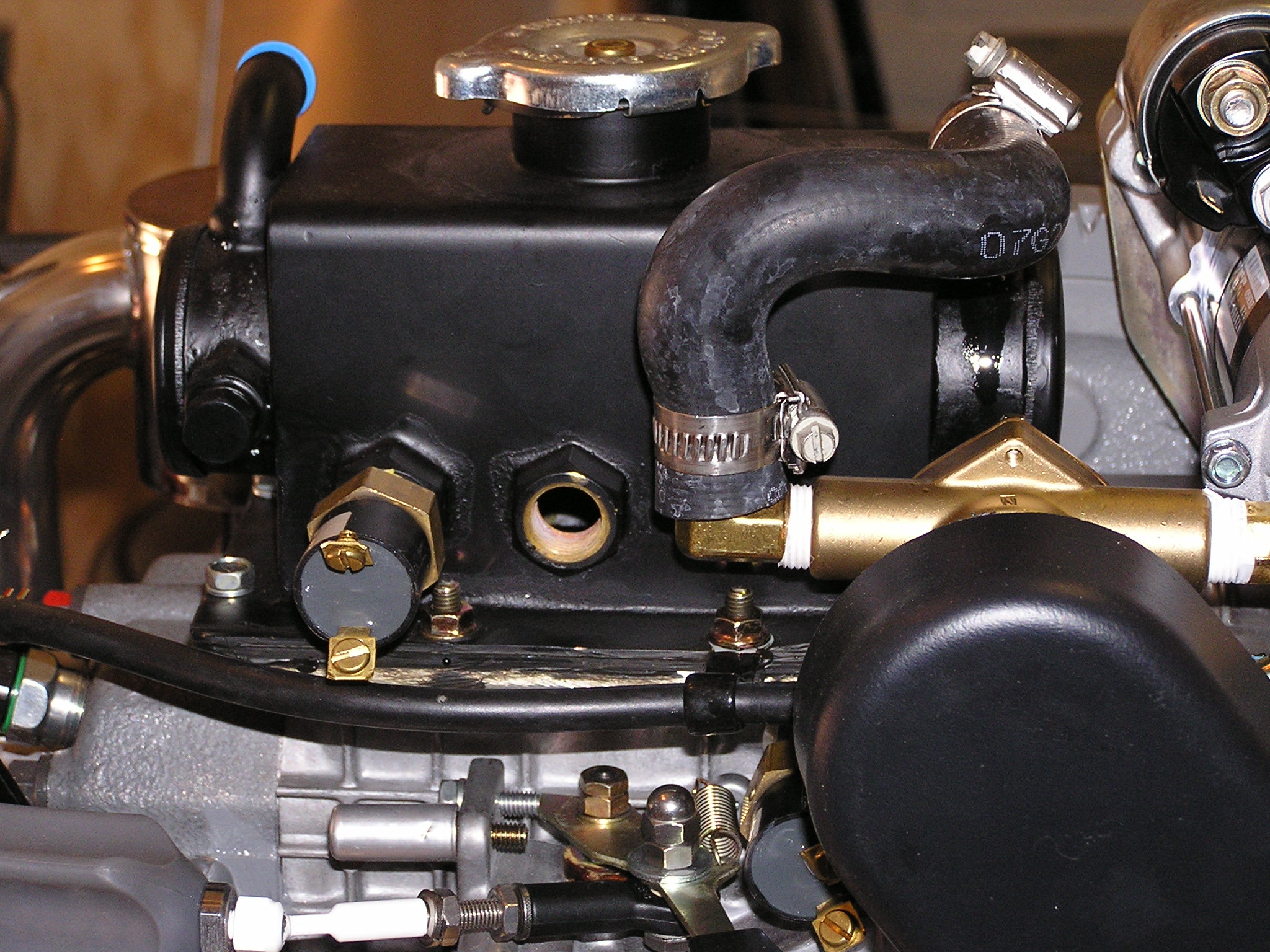
First I assembled the engine with its major components installed.
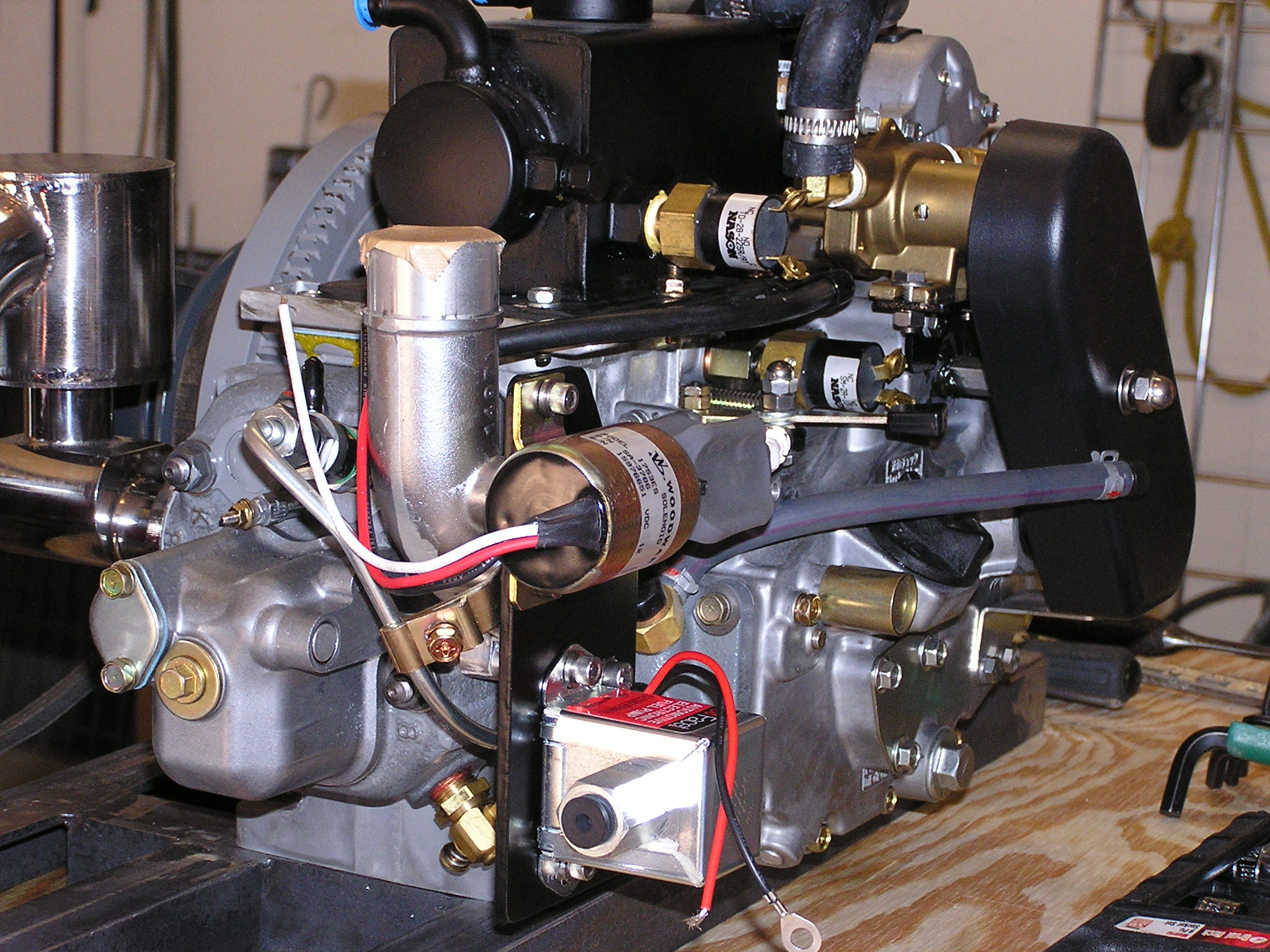
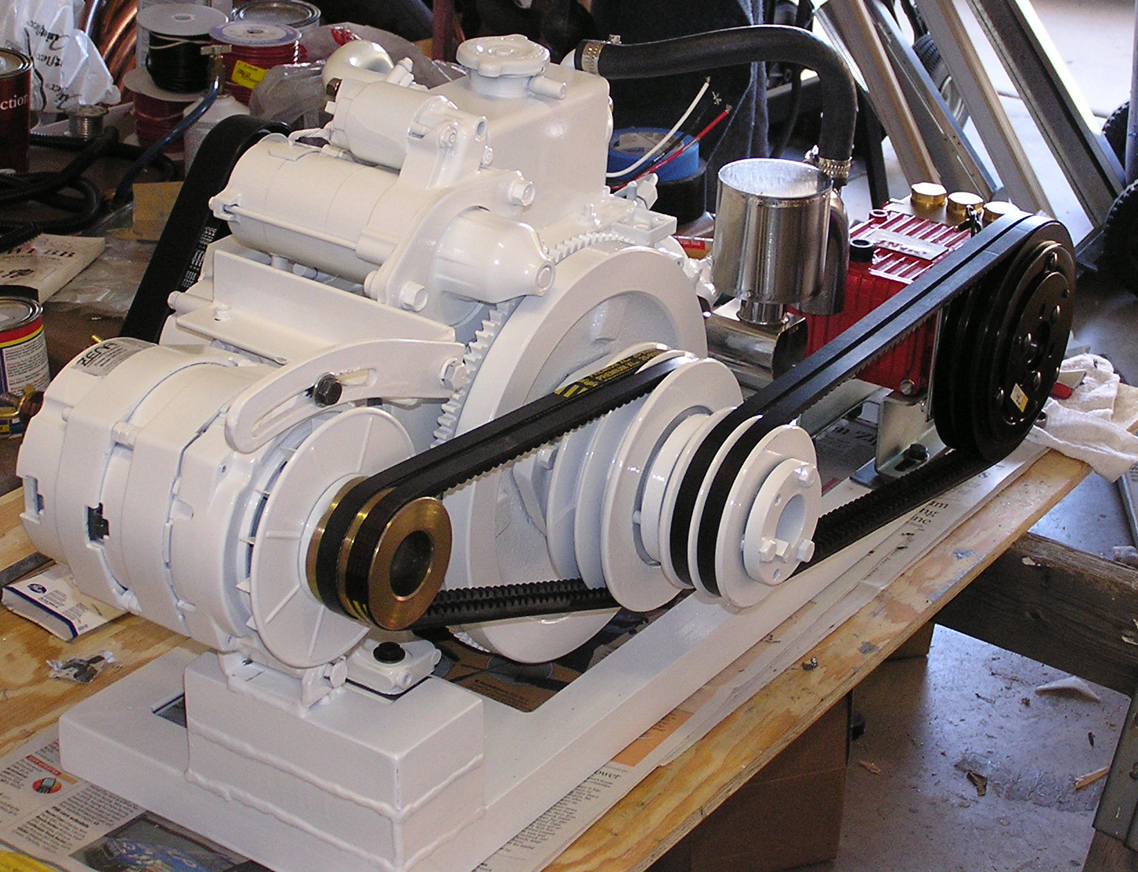
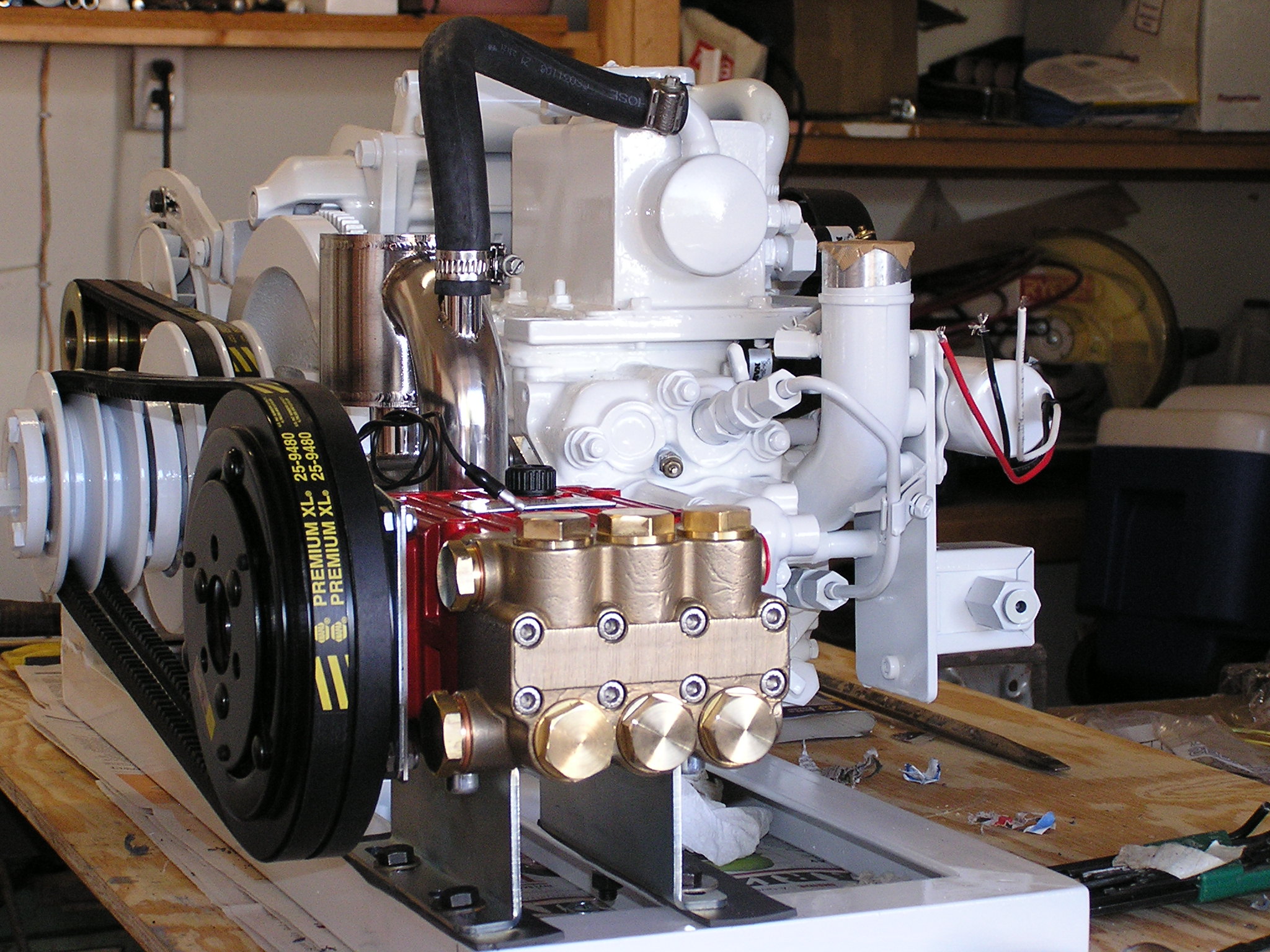
I built a base to mount the engine, pump and alternator on and then laid out the positions. It is a simple angle iron frame. The engine and high pressure pump are bolted directly to this frame. The alternator is mounted on a mount welded to this frame, the mount and adjustment arm was supplied by Zena the manufacturer of the alternator.
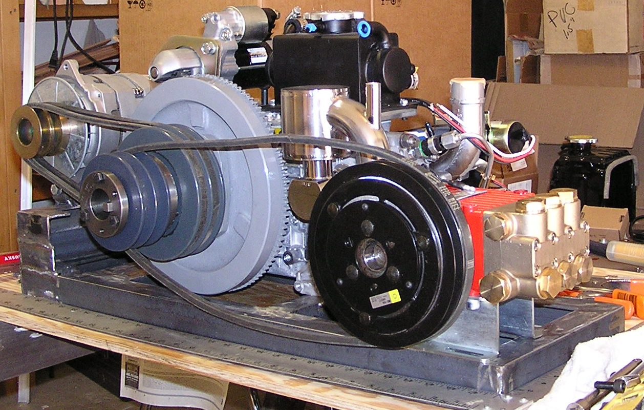
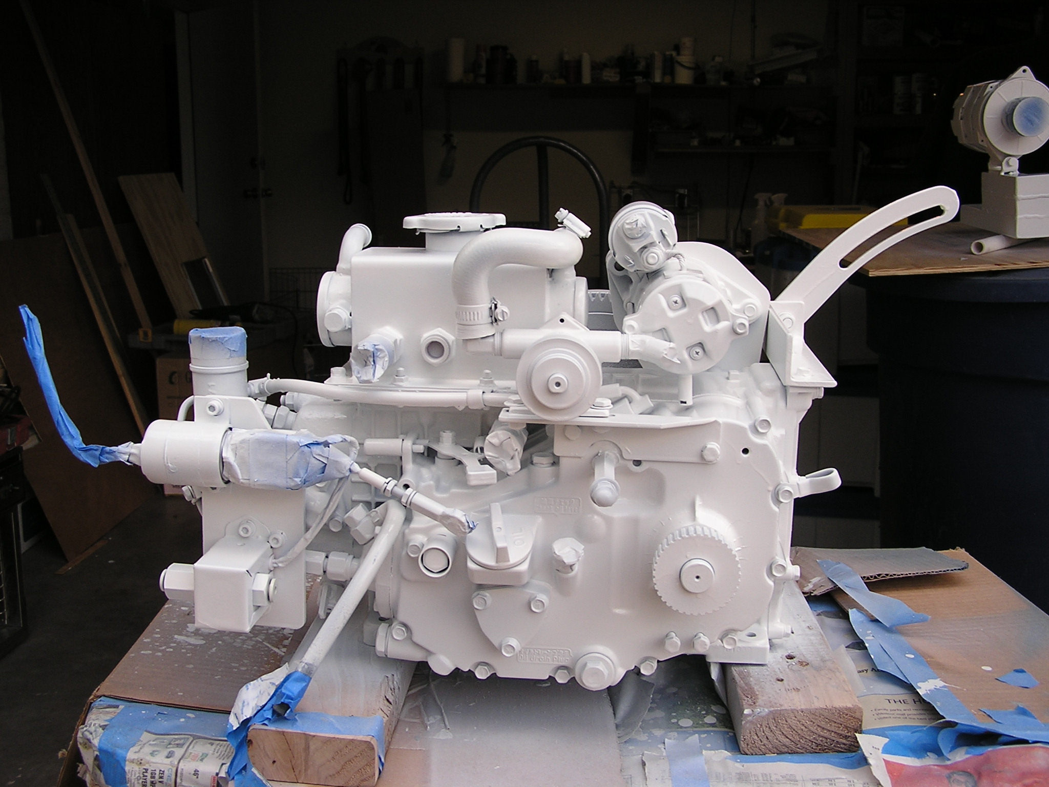
After determining where everything would be mounted, it was disassembled for painting.
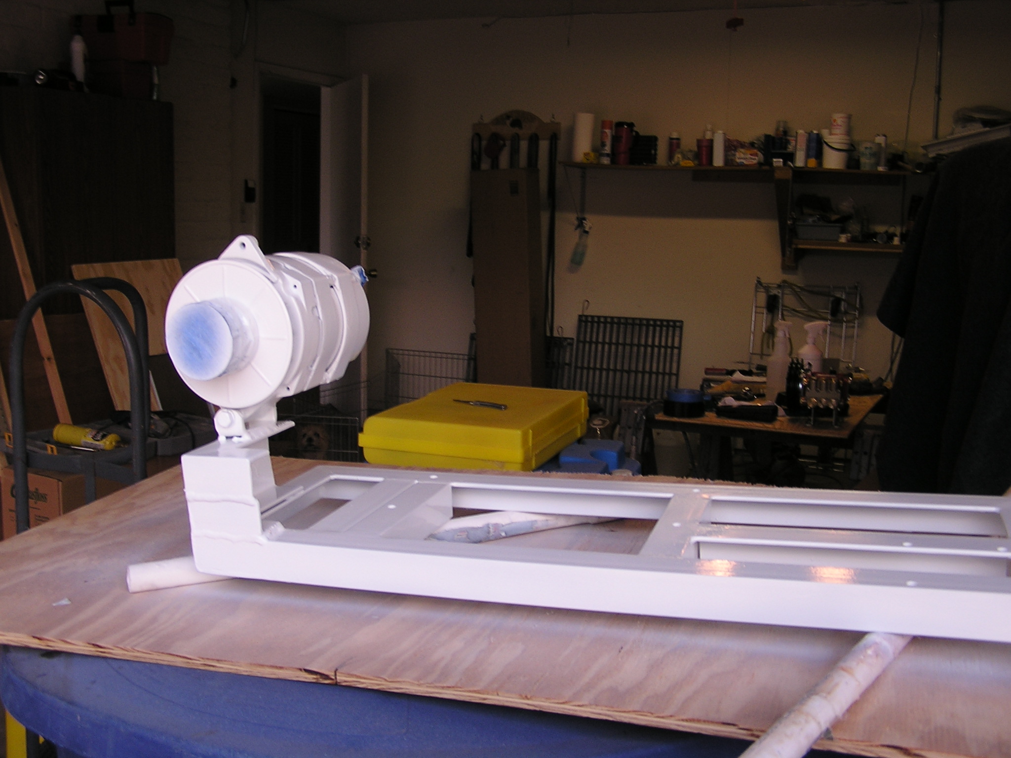
I use POR15 which was touted as an engine paint that was tough and heat resistant. It also was suppose to treat the metal and prevent rust. We shall see.
Then it was reassembled and lined up in a SS drip pan that it will be mounted in.
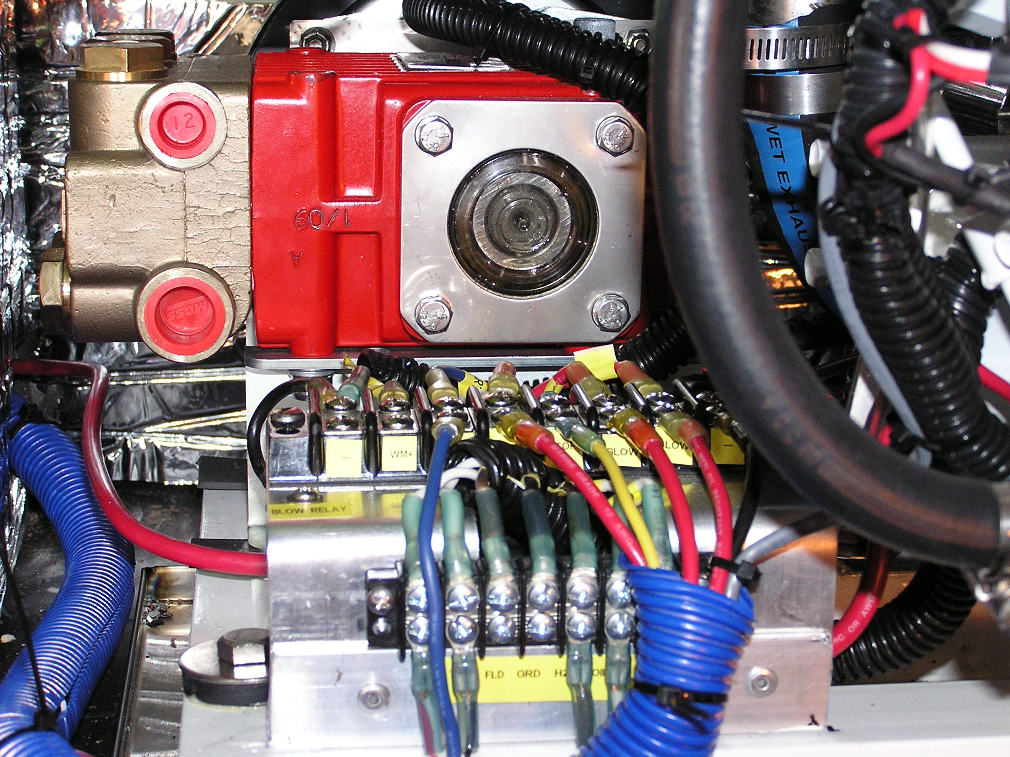
Wiring and Controls
Then it was time to wire the engine, alternator & water pump. The engine speed is controlled by the throttle solenoid and it is set to run at 2600 rpm. This is easily set by adjusting the linkage to the speed wanted. I wanted to enclose the genset completely and not have to access it to start or adjust it. So that required some automatic controls.
I used an oil pressure switch that had to close for the unit to start and a water temperature switch that has to be closed for the unit to run. A blower is automatically turned on when the engine starts. The air inlet is located so the fresh air enters at the rear of the alternator (where the diodes are).
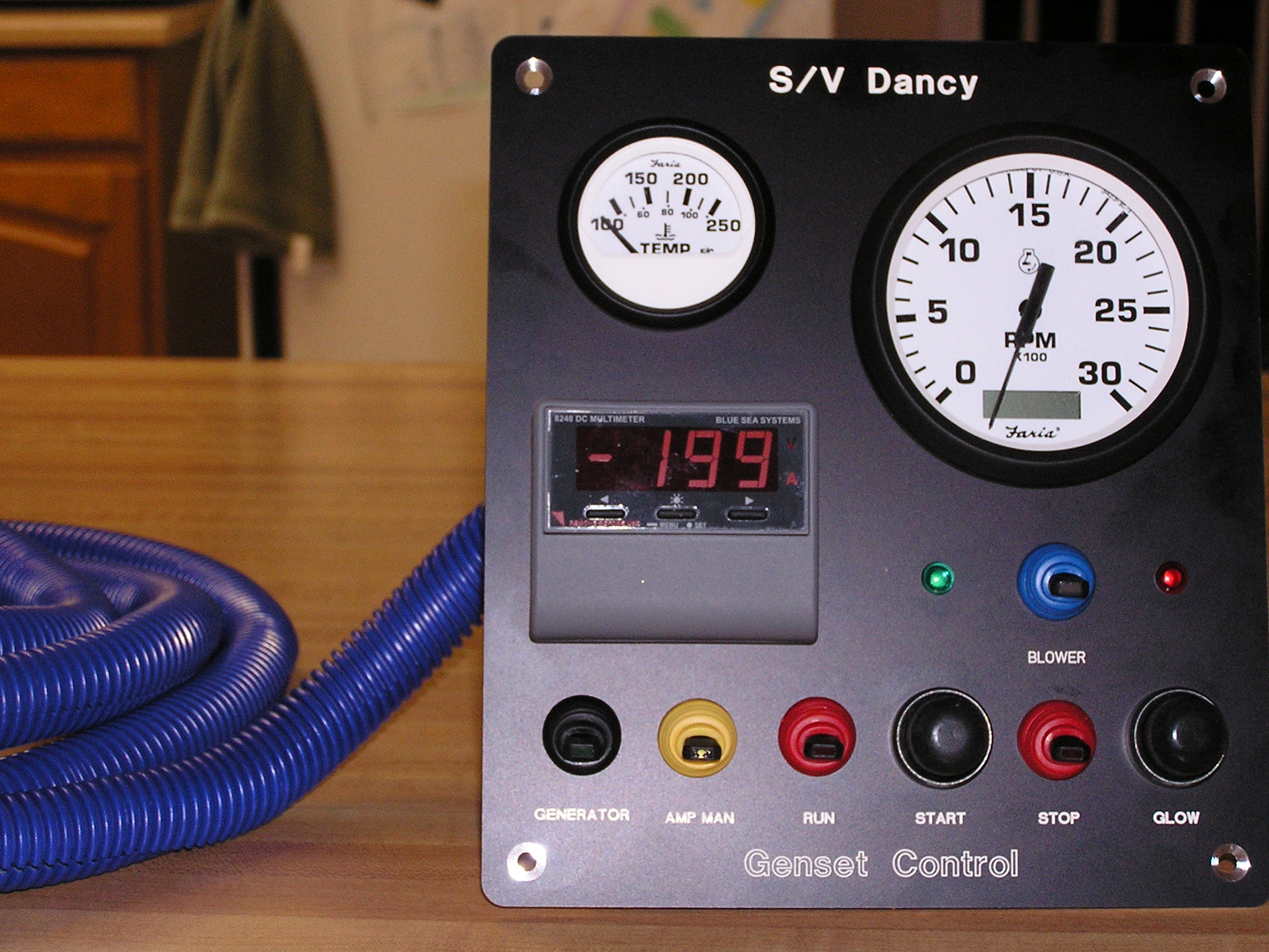
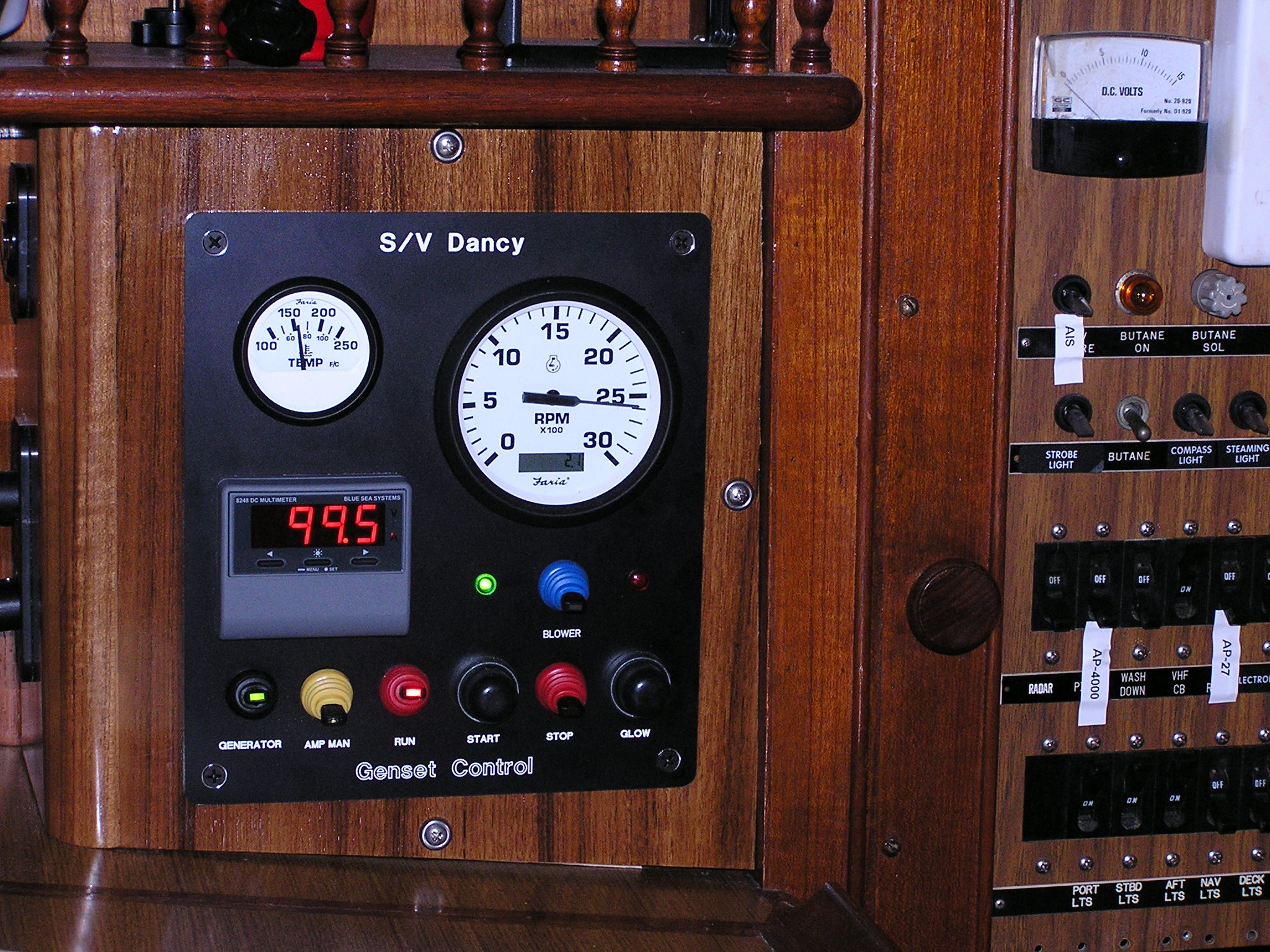
The alternator has a DC shunt with a shunt shifter to monitor the amperage output, and is shown on the control panel. The alternator output is fused and is fed to the batteries by 2/0 cable. The alternator is controlled by a Balmar MC612 regulator with temperature monitoring and the "amp manager" function is run though the control panel. The amp manager function can be used to reduce the output if needed to run the water maker at the same time as the alternator.


The blue conduit above goes to the control panel at the Nav desk. I wanted the control panel to contain all of the pertinent information and controls without being too complicated. All of the control panel and switching is done with simple electromechanical devices. They could all be bypassed or simply replaced if they fail. The control panel was designed with the free software from Front Panel Express and I'll use them to build the control panel for the water maker also.
Installation
Now it was time to install it all in the boat. When I designed and installed my starboard fuel tank I wasn't thinking about a generator of any kind. Therefore I didn't leave a lot of room above the tank. I only had 17" of height above the tank to install something. That's why this unit has the alternator and water pump mounted out to the sides of the engine, plus it puts opposing forces on the output shaft.
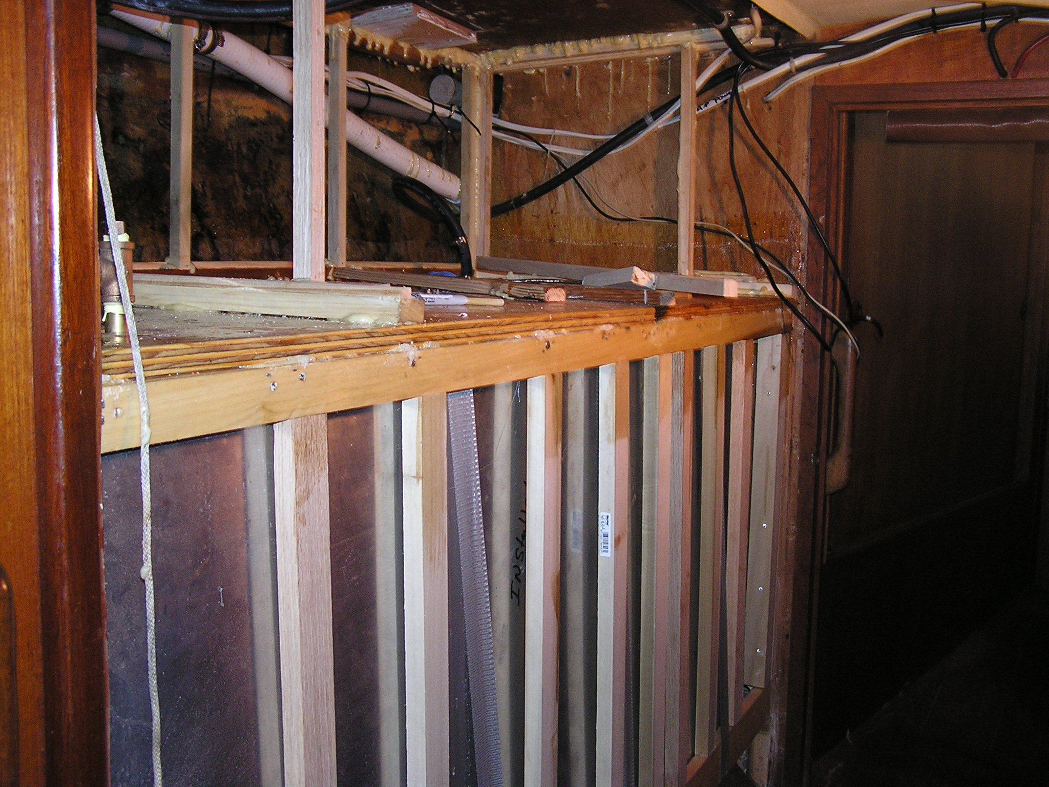
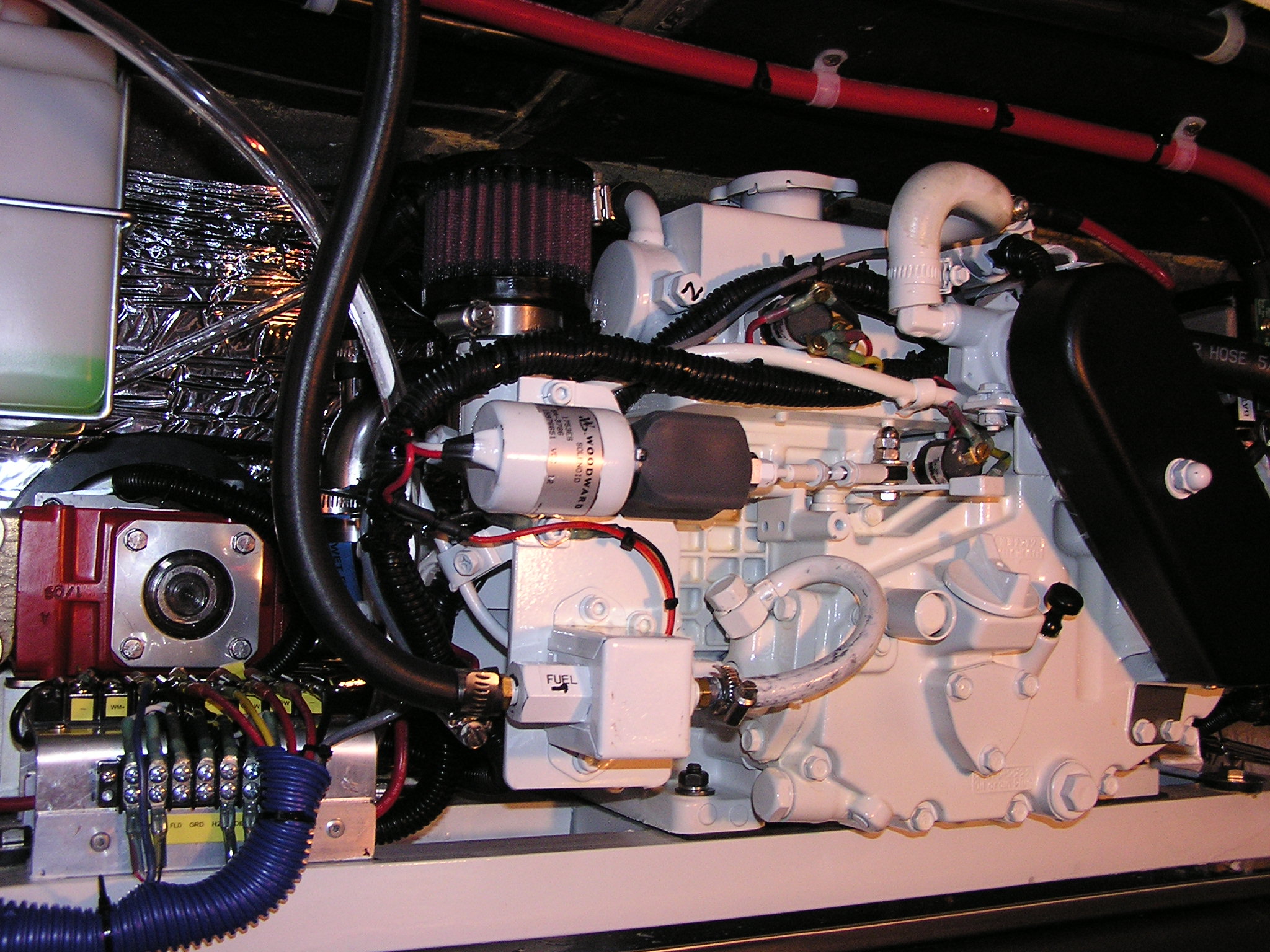
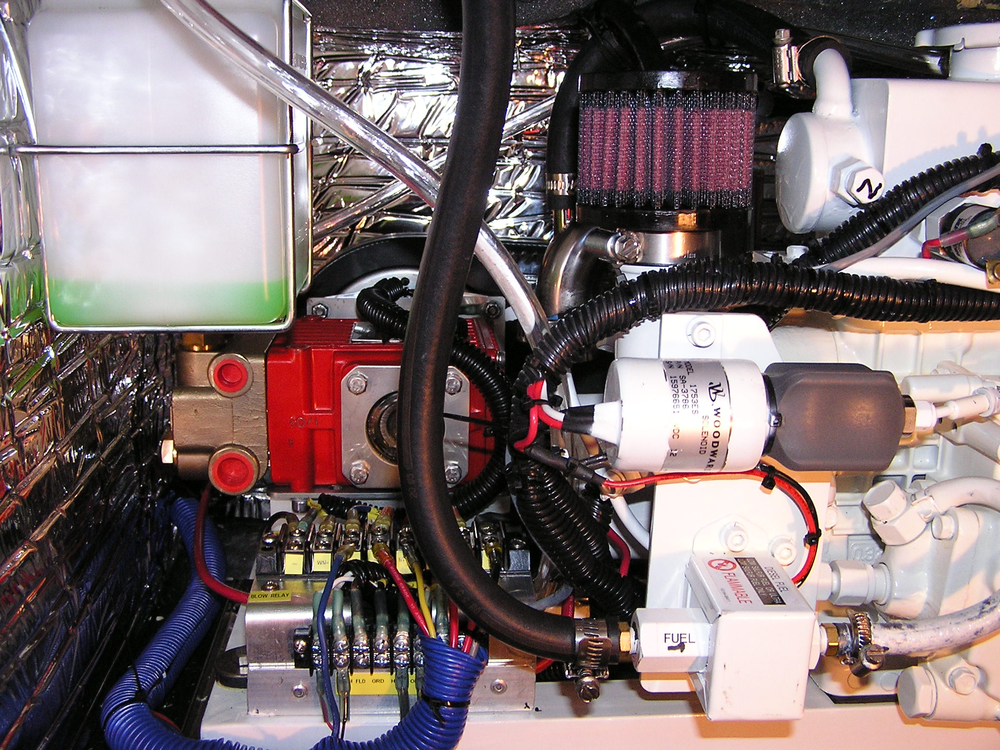
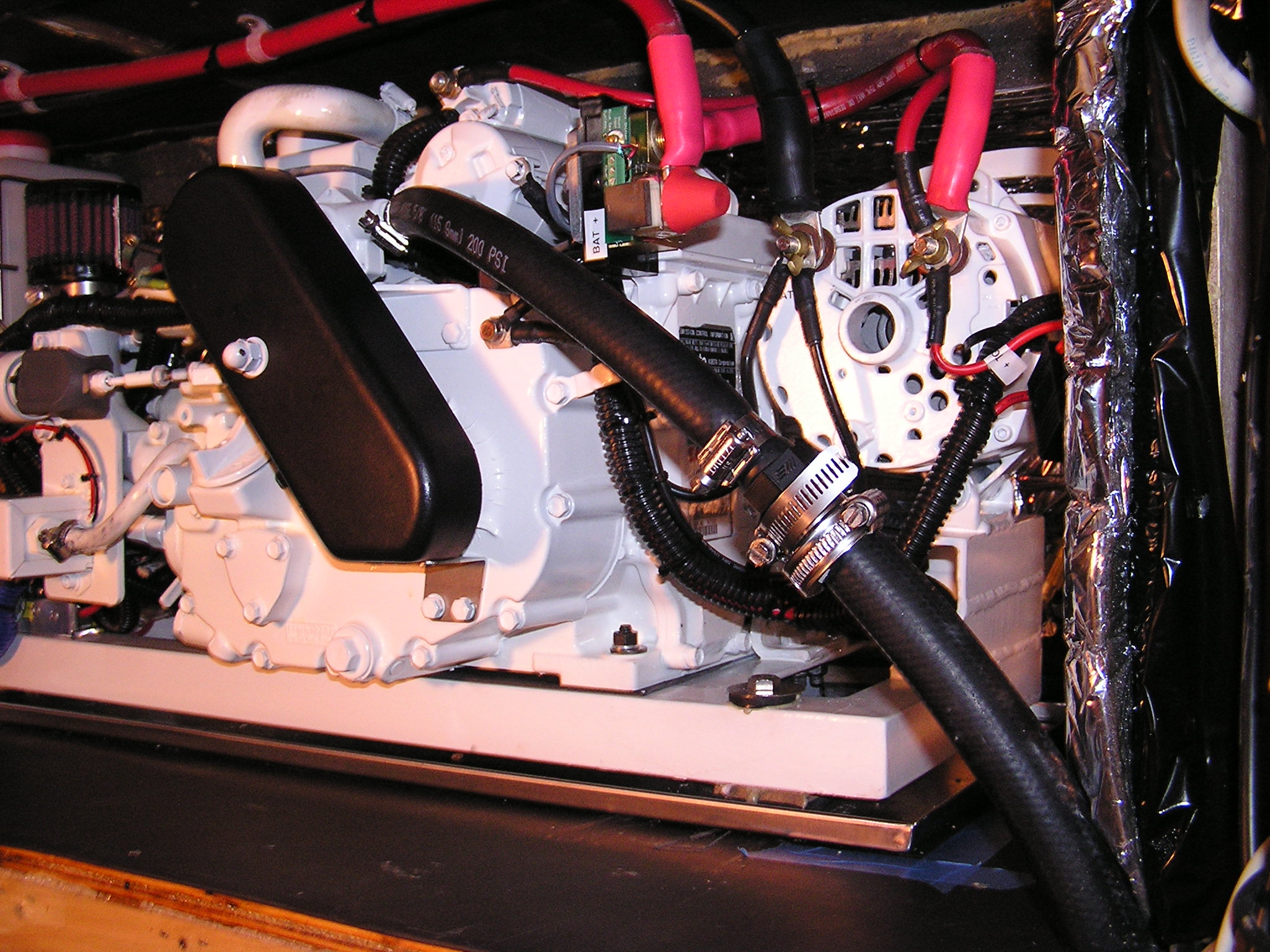
Building the enclosure here required rerouting the deck drains, some tank vents, and some wiring. Below is the unit installed and operational, but not enclosed.
Here's the control panel installed and operating.
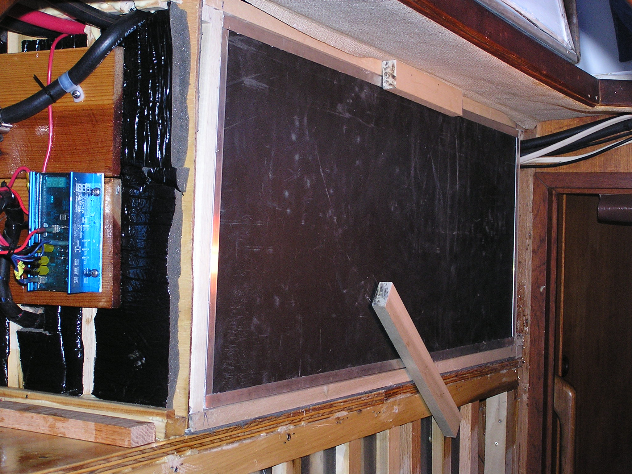
And the genset enclosed with the sound shield but I haven't replaced the finished bulkhead yet. Note the regulator is located outside of the sound enclosure to keep it cool.
Exhaust System
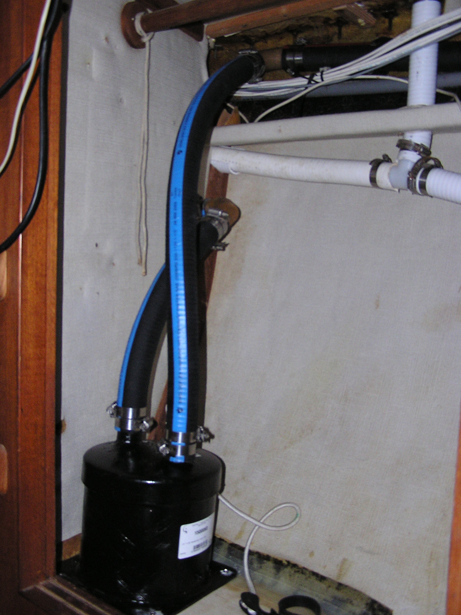
The exhaust runs out the stern and has a waterlift muffler in the aft cabin locker and a check valve in the run out to the stern to prevent any chance of water backing up the exhaust.
Reflections and Recommendations
I still have plenty of finish work to complete this project, but so far it all works as well as expected. If I were to start over I'd have reduced the size of the starboard fuel tank and left myself enough room to better isolate the gensets mounts. There is a good amount of vibration transmitted into the boat, the exhaust is pretty much silent. The main noise on the outside of the boat is the bilge blower used to exchange the air in the enclosure. The noise in the boat is less than the main engine, but not as quiet as I would have hoped.
I choose the 150 amp alternator so I could charge batteries and make water at the same time, however this engine could handle a larger alternator. I wanted to keep everything on the conservative end so as to increase reliability. On the engine I would have liked to have had a custom machined sheave set made of aluminum, to save weight on the shaft of the engine. It also would have allowed a more compact unit.
All in all, I believe this is a feasible project for most "handy" people.
A variety of engines could be used as well as alternators. The 2 cylinder Kubota would be my choice next time with space permitting. I also like the Next Generation 3.5 KW AC unit and would consider that for an AC system.
Project: S/V Dancy-1980 KP44 #279
View Complete Photo Album of Build & Install on Peterson Cutter Discussion Group (login required)